
By Backyard Provider Editorial Team
Industrial Equipment & Fluid Power Insights
Designing a central hydraulic system to support a sprawling 130,000 square-foot production facility is no small feat. It presents a range of engineering challenges—from integrating portable hydraulic power units for OEM machinery to managing heat dissipation across hundreds of feet of piping. In this detailed exploration, we walk through how one customer’s unique facility requirements led to an innovative hydraulic system design that delivered measurable performance gains and long-term reliability.
The Problem
The customer’s existing hydraulic setup had been originally designed and installed over 30 years prior. Through decades of service, the infrastructure had accumulated a range of issues: fixed-displacement gear pumps provided flow and pressure throughout the building, but a significant amount of energy was consistently wasted in the form of heat generated by oil flowing over relief valves at the central unit. Most of the tubing that ran throughout the facility featured high-pressure, rigid-walled segments and areas exposed to fluid contamination.
Despite the hydraulic circuit’s apparent simplicity, the company could not manage the ingress of contaminants into the hydraulic fluid effectively. The result was mounting downtime, escalating repair costs, and servo valve failures that demanded increasingly frequent maintenance cycles. After years of enduring these setbacks, the customer was ready for a complete overhaul—one that prioritized energy efficiency, reduced component failures, and modernized the entire system architecture.
System Requirements & Specifications
The specifications for the new central hydraulic system were extensive and carefully detailed. They demanded a much more refined approach than the original installation. The key technical requirements included:
Reservoir
15,000-gallon capacity
Large-volume fluid storage with closed-loop air exchange
Flow Rate
Up to 1,296 GPM
At 300 psi or 486 GPM at 1,000 psi capacity
Pressure
0–2,500 GPM variable
Stable system pressure with 4-port capacity
Piping
Engineered stainless steel
Knowledgeably routed throughout facility
Temperature
112°F to 130°F range
Maintained during continuous operation
Cleanliness
ISO 13/11/7
Strict contamination control standards
Additional specifications called for ambient oil temperature tolerance between 112°F and 130°F during operation, water content maintained below 100 ppm, and a continuous 24/7 operational lifecycle with a target system life expectancy of at least 30 years. Beyond these known constraints, the engineering team had to contend with limited space in the design for the pump room, compressing the hydraulic footprint of the project into a tight physical envelope.
Design Challenges & Engineering Solutions
The project involved extensive collaboration among stakeholders. Design review meetings with the facility’s general contractor, design architects, structural engineers, and representatives of other building trades ensured alignment at every stage. The final result was a system built around several core components:
1 Reservoir (1,700-gal)
8 Pump/Motor Groups
Recirculation & Cooling
Vacuum Dehydration
Particle Counter
30 Accumulator Stations
Reservoir Design
The large-capacity reservoir had to be engineered to comfortably support the variability of end-use case pipetting and corresponding loop parameters. The overall dimensions of the reservoir were approximately 7 feet high by 7 feet wide by 35 feet long.
One of the real design challenges was deploying the large 504-stainless steel reservoir inside a building under construction while accommodating a culturally small pipe wall thickness of 8 inches. It functioned as a diffuser down from the center of the tank, allowing the reservoir to effectively “capture” the return fluid while maintaining separation of an oil return line from the center of the tank from the pump suction supply. Fluid was settled on either side.
This was truly a unique reservoir design that required a structured 3D CAD model. Three distinct element-level analyses of the reservoir for eigenvalue frequencies for vibration modes, stress concentrations on the structure, and applied pressures were performed to validate the design before fabrication commenced.
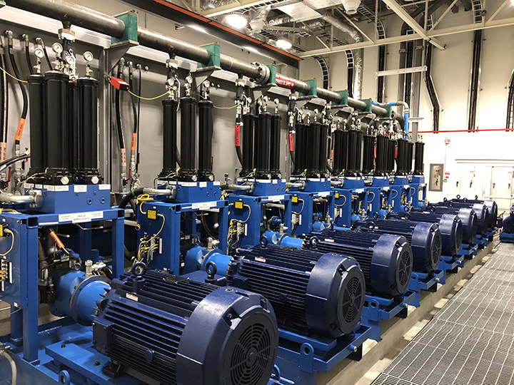
Pump & Motor Group Configuration
The engineering team needed to design a system that addressed the user’s ability to perform manual swapping of individual components. The pump solution for the new central hydraulic system included pressure-compensated piston technology with load control for 24/7 year-round operation. By partnering with a reputable system pump control manufacturer, the team’s experience with large system applications and its load-sharing expertise led to a solution that included the latest in electric and electronic power delivery.
While piston pumps are more expensive than their gear pump counterparts in comparable hydraulic systems, they provide longer life through higher pressure and longer continuous duty cycles. The load-sensing system ensures the pump reduces both flow and pressure to match the actual load requirements of the system at any given moment.
Each of the 16 pumps was coupled to a 300-hp inverter-duty rated motor. These particular pump/motor groups each incorporated an independent suction strainer. The system included both inlet and outlet line spin-on filter assemblies rated to 5,000 psi with 6-micron elements. The team placed eight pump/motor groups on each side of the large main reservoir.
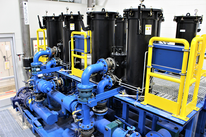
Recirculation & Cooling Strategy
Another significant challenge was meeting the stringent oil cleanliness requirement of 13/11/7 per ISO 4406. An oil recirculation skid with kidney-loop filtration systems was needed. This recirculation skid provided a continuous flow of all filtered oil, separated from the main supply pressure lines, and directed the filtered oil up to the four 4-million BTU heat exchangers installed on the roof of the new building.
Key Challenge: The roof-top heat exchangers on the roof were exposed to weather conditions typical of the Midwestern U.S. Freeze-point ambient winter temperatures reaching -15°F to -20°F contrasted sharply with the requirement of keeping oil temperature between 112°F and 130°F during spring-to-fall operations, regardless of weather conditions outside.
The solution was to provide the recirculation skid’s pump individually cycled on or off to sweep the hydraulic system’s temperature. Variable frequency drives (VFDs) on each of the four cooling pumps on the recirculation skid correlated with a variable frequency drive setup. The VFDs provided precise speed control for current oil and energy efficiency needs. Since the fluid temperature was being monitored in numerous places throughout the hydraulic system, the team could regulate the amount of fluid routed to the rooftop cooler, ensuring that the cooling fluid is effectively kept free of temperature fluctuations during the production process.
Vacuum Dehydration & Particle Control
Water is one of the most common and destructive contaminants of industrial and oil-reliant equipment. Water entry into the oil accelerates corrosion when temperatures drop, it displaces key additives, and can cause direct corrosion of steel components in the hydraulic system.
The team overcame this challenge by incorporating a properly sized vacuum dehydration unit. Vacuum dehydration is the only comprehensive method to effectively remove water vapor and other contaminants from the oil. Through careful temperature stabilization in combination with low filtration, oils can be kept in a near-new operating condition.
The vacuum dehydrator integrated into the system was a stand-alone unit mounted on a structural steel tower with a compact design. It is capable of processing more than 1,200 gallons per hour at 1,100 cps and contains an entire particle counter to monitor the oil cleanliness level. An onboard PLC communicates via Industrial Ethernet to the hydraulic system’s main PLC, ensuring continual fluid data exchange.
Secure Flow Architecture
Given the central hydraulic system’s significant potential flow volume of up to 2,300 GPM, the engineers combined two sets of large-caliber Victaulic couplings on a single steel-bore main filtration skid. Each of the four total laterals is populated with ten 5,000 psi high-flow filter elements to handle the volume demands.
Accumulator Integration
With the possibility of sudden flow changes due to circuit stands starting and stopping, the engineers had to account for the resulting “shocks” in the hydraulic system. The solution was to incorporate strategically positioned banks of accumulators that serve to absorb and store energy. The total of 30 accumulator stands throughout the new facility provide an evenly distributed amount of shock absorption capacity throughout the system.
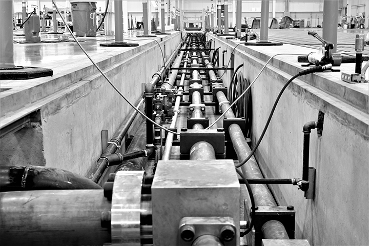
Engineered Piping Network
Another challenge was to constrain noise and vibration transmitted through the piping via improper planning. Selecting the correct pipe size for a hydraulic system is critical to obtaining maximum performance and life from hydraulic components. Undersizing fluid lines results in high-pressure loss and heat, overflowing line diameters increases the cost of the system. In typical applications, flow velocities should be kept as follows:
2–4
ft/sec — Suction
6–10
ft/sec — Return
15
ft/sec — Medium Pressure
20–25
ft/sec — High Pressure
The facility used almost two miles of piping, located in floor trenches throughout the production area, paired with 40% weld-free connection technology. This approach eliminated the risk of corrosion due to stress cracks during welding and increased the lifespan for the piping system. The team used facility CAD data in conjunction with the CAD-based routing tools to manufacture and cut the precise tube segments, creating removable flanged joints that gave the pipe fitters greater flexibility during assembly. This reduced installation time and will simplify maintenance, reduce operating costs, and improve safety.
Providing proper line sizes means improved performance of the hydraulic test equipment throughout the facility. It makes flow more laminar, reduces the effect of shock, decreases potential leak points, minimizes fittings and connector failures, and reduces heat generation.
Controls Architecture & Monitoring
For this central hydraulic system, the controls design and integration were a core part of the turnkey installation. Operating the hydraulic system’s 24/7 year-round required redundant PLCs. The integrated controls also included real-time monitoring, records, and requests to system performance and health. The entire system is monitored and displayed on the system’s user operator interface, including:
110+ multiple emergency control stops
System flows and pressures monitoring
Reservoir fluid levels & oil temperature
Multiple vibration & bearing temp sensors
Differential pressure sensors across filters
Multiple sump detection sensors
Safety interlocks, fire alarms & sprinkler detection
Status monitoring of all pumps, fans & valves
The system also allows all user-settable parameters along with real-time system performance data captured on the operator’s interface. Making the machine interface greatly enhanced the customer’s efficiency in maintaining the system and maximizing uptime.
The project addressed the customer’s system requirements for flow response, pressure compensation, and energy conservation. The customer received a turnkey custom hydraulic solution tailored to their unique application. Parker was the source of many system components, including filters, valves, accumulators, aftercoolers, proportional valves with controllers, hoses, and fluid connectors.
The Results
The new system addressed all of the customer’s longstanding concerns with their legacy hydraulic infrastructure. The measurable outcomes included:
Using sound fluid power design principles, the new central hydraulic system achieved measurable benefits with a much longer projected lifespan than the original installation. Through proper sizing of supply and return fluid lines, accurate pressure-compensated controls for pressure monitoring, and multiple outputs for level and temperature monitoring, the new system avoided the excessive energy usage followed by a valve-controlled application that plagued the earlier system.