
In This Guide
- ▶ Why Go the DIY Route
- ▶ Sizing Your Mini Split System
- ▶ Key Features to Look For
- ▶ Choosing the Right Unit
- ▶ Pre-Installation Preparation
- ▶ Step-by-Step Installation
- ▶ Common Mistakes & How to Fix Them
- ▶ Cost Breakdown
- ▶ Real-World Performance
If you have ever dealt with a room in your home that simply refuses to stay comfortable — scorching in summer, freezing in winter — you know the frustration. A mini split air conditioning system is one of the most efficient, versatile solutions available to homeowners today. Better yet, with the right preparation, you can install one entirely on your own.
This guide walks you through a complete, real-world DIY mini split installation from beginning to end. We will cover system selection, sizing calculations, preparation, the actual hands-on installation process, the mistakes that can happen along the way, and how to correct them. Whether you are cooling a garage workshop, a sunroom, or any space that your central HVAC simply cannot reach, you will find everything you need right here.
A professional installation of a comparable system can easily run $4,000 to $5,000. A well-planned DIY approach can cut that figure significantly — to roughly $2,000 including equipment, tools, permitting, and certification. Let us break down exactly how.
Why Go the DIY Route
There are several compelling reasons homeowners choose to install a mini split AC system themselves rather than hiring a contractor. Understanding both the advantages and the limitations will help you decide whether this path is right for your situation.
Advantages of a DIY Install
Hands-On Satisfaction — There is a deep sense of accomplishment in tackling a complex project with your own skills. If you enjoy building, wiring, and problem-solving, HVAC work is the natural next frontier.
Learning Opportunity — Air conditioning installation is surrounded by a certain mystique. In reality, the core concepts are straightforward. Doing it yourself gives you an invaluable understanding of how your system works, which pays dividends in future maintenance.
Significant Cost Savings — The labor component of a professional HVAC installation is substantial. Depending on your region, doing the work yourself can save you $2,000 or more.
It Is Often Perfectly Legal — In many jurisdictions, homeowners can perform HVAC work on their own property with the correct permits. Check your local regulations before proceeding.
What to Consider Carefully
Legal Restrictions: Not every jurisdiction allows homeowner-performed HVAC installations. In some areas, this work must be completed by a licensed professional. Always verify your local building codes and permitting requirements first.
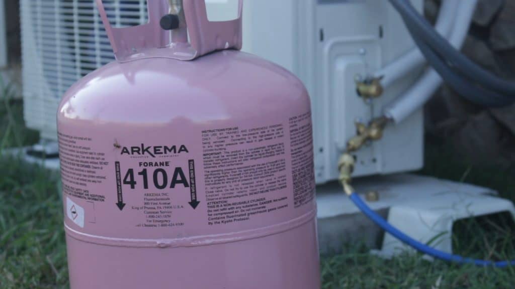
Safety Considerations: You will be working with pressurized refrigerant and typically a 240-volt electrical supply. Both require careful, knowledgeable handling. If your system uses R410a refrigerant, all equipment must be rated for the higher working pressures involved. Do not take shortcuts with safety.
Refrigerant Certification: In the United States, EPA Section 608 Type II certification is required for anyone working with R410a refrigerant — including homeowners performing their own service or repair work. Refrigerants are harmful to the environment when vented. This certification typically involves about a week of study and an exam that can be taken at local HVAC supply houses.
Warranty Implications: Some manufacturers may challenge warranty claims on units not installed by a licensed contractor. Thorough documentation of your installation — photographs, measurements, a detailed checklist — can help mitigate this risk. Your EPA certification may also serve as a professional qualification in some cases.
Ultimately, if you are confident in your electrical and mechanical skills, willing to obtain the proper certifications, and your local codes permit homeowner installation, a DIY mini split project is entirely achievable. If any of those factors give you serious pause, it is better to hire a professional and do it right than to cut corners and risk your safety or your investment.
Sizing Your Mini Split System
Before ordering any equipment, you need to determine the correct system size for your space. A unit that is too small will struggle to keep up on the hottest or coldest days. A unit that is too large will short-cycle, wasting energy and failing to dehumidify properly.
Begin by addressing the fundamentals. Heat is energy, and an uncomfortable room is one that accumulates too much of it in summer or loses too much in winter. Before jumping straight to a cooling system, take stock of your space. Insulating walls, ceilings, and especially garage doors can dramatically reduce the load your mini split needs to handle. In one real-world case, adding ceiling insulation alone brought a garage from 95°F down to outdoor ambient temperatures — a huge improvement that allowed a smaller, more efficient unit to handle the remaining load.
Use an online BTU calculator to estimate your heating and cooling loads. Factor in room dimensions, insulation levels, window area, sun exposure, ceiling height, and local climate extremes. For a well-insulated garage workshop of around 400 to 500 square feet with moderate sun exposure, a 9,000 BTU unit is typically sufficient. Larger, poorly insulated, or sun-battered spaces may require 12,000, 18,000 BTU, or more.

If your space will serve as a year-round workshop, office, or living area, remember to calculate the heating load as well. In cooler climates, the heating requirement can actually exceed the cooling load. For instance, maintaining 55°F in a moderately insulated garage when it is 22°F outside may demand around 8,400 BTU, while maintaining 75°F when it is 91°F outside might only require 6,100 BTU. Do not assume your application is cooling-limited without running the numbers.
Also keep in mind that any electrical equipment running in the space — lighting, power tools, computers — generates heat. In summer, your mini split must work against this additional thermal load. In winter, that waste heat supplements your heating, potentially letting you maintain a warmer indoor temperature than you might otherwise expect from the unit alone.
Key Features to Look For
Not all mini splits are created equal. When evaluating your options, pay close attention to these critical features.
Heat Pump Capability: If you intend to use the space year-round, heat pump functionality is essential. A heat pump reverses the refrigeration cycle to move heat from outside air into your room during winter. This is far more energy-efficient than resistive electric heating.
Energy Efficiency (SEER Rating): SEER stands for Seasonal Energy Efficiency Ratio. Higher is better. Standard units may fall in the 14 to 18 SEER range, while premium units reach 23 SEER or above. A unit near 25 SEER will use considerably less electricity over its lifetime, which reduces both your energy bills and your carbon footprint.
Inverter Technology: To achieve high SEER ratings, you want a unit with inverter-driven compressor technology. Rather than cycling on and off at full power, an inverter system runs continuously at variable speeds, adjusting its output to match the exact demand. This eliminates the energy wasted by constantly restarting and reduces temperature fluctuations for a more consistent comfort level.
Operating Temperature Range: Air conditioners lose efficiency as outdoor temperatures rise, and heat pumps lose efficiency as temperatures fall. Every unit performs differently across its operating range. Before purchasing, verify the manufacturer's performance data at the extreme temperatures you expect in your climate. You may need to contact the manufacturer directly for detailed performance curves, as this information is not always available on product listing pages.
Choosing the Right Unit
Once you have defined your BTU requirements, desired features, and budget, it is time to narrow down the options. There are numerous manufacturers producing units that meet common residential criteria. When comparing, look at manufacturer documentation, customer reviews, the price of the unit itself, and shipping costs. Some units ship on pallets and may incur freight delivery charges.
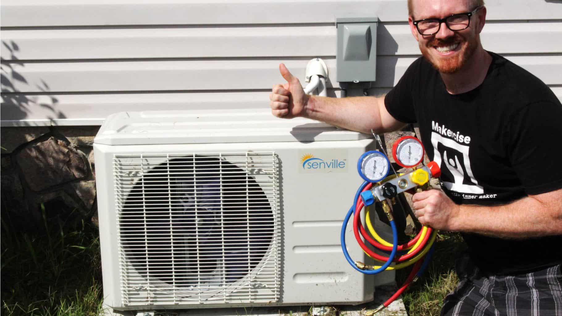
The Senville LETO series is a strong option for homeowners who want high efficiency, heat pump capability, and a system that is well-documented for DIY installation. These units come with a comprehensive piping kit, making it possible to complete the installation with minimal additional purchasing.
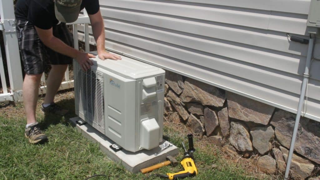
Expect a typical shipment to arrive in two or three boxes: the indoor air handler, the outdoor condenser unit, and the lineset and accessories. The outdoor condenser unit is heavy, so plan to have a second person available for moving and positioning it.
Pre-Installation Preparation
Before you so much as pick up a drill, there are two administrative items that must be in order.
Permits: In most jurisdictions, installing a mini split system that includes electrical work requires a building permit. The cost varies but is typically modest — often around $50. Pull the permit before you start. This protects you and ensures your work will be inspected for code compliance.
EPA Certification: If your system uses R410a refrigerant (most modern mini splits do), the EPA requires Section 608 certification for anyone who works on the refrigerant system. You can obtain this through a proctored exam at many HVAC supply stores. Study materials are readily available, and most people with a basic technical background can pass within a week of study. The exam fee is typically around $100. With your certification and permit in hand, your installation is fully above board.
Step-by-Step Installation
⚠ Important
Regardless of which brand you choose, always follow the manufacturer's installation instructions for your specific unit. This guide is meant to supplement — not replace — those instructions. Document every step with photos and measurements. A thorough checklist is invaluable for troubleshooting and for supporting any future warranty claims.
Placement Planning
The first physical task is to plan where each component will go. The indoor unit should be mounted centrally in the room for even air distribution, typically about 7 to 8 feet above the floor. The outdoor condenser needs a stable, level surface with adequate clearance for airflow on all sides.
Factor in the routing path for the copper lineset, the electrical cable, and the condensate drain line. If the indoor and outdoor units are on the same wall, you may only need a short lineset of 15 to 16 feet. Greater distances require longer linesets, and every system has a maximum allowable distance — check your specifications carefully.
Consider how you will route lines through or around the building. Your three basic options are: an exterior line cover (raceway) that keeps everything tidy on the outside of the house, an interior channel concealed behind drywall, or a direct pass-through behind the indoor unit. Each has trade-offs in terms of aesthetics, difficulty, and the amount of finish work required afterward.
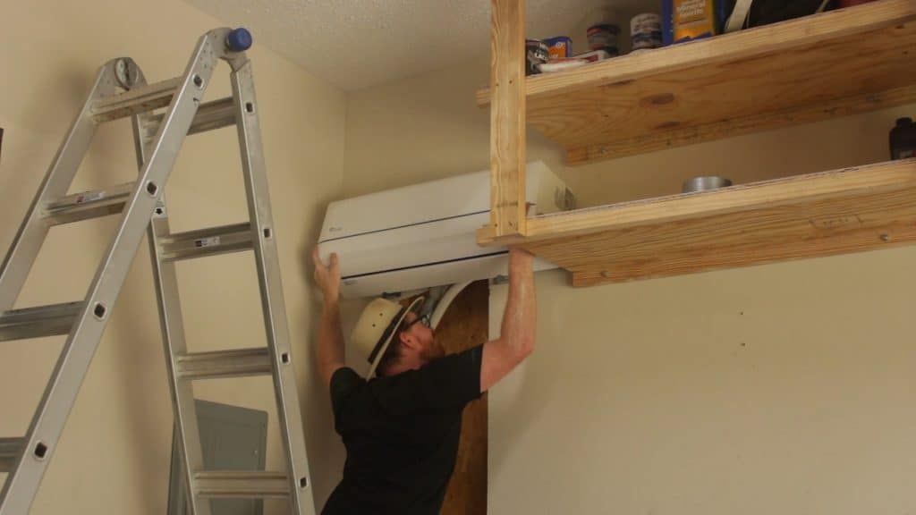
Mounting the Indoor Unit
Your unit will include a mounting bracket and either a template or dimensions for positioning it. Use the actual indoor unit to verify critical measurements if the instructions are ambiguous. Ensure the bracket is perfectly level — even small misalignments can affect drainage and aesthetics.
Drill an angled hole through the wall (angling downward toward the outside) if you are routing the lineset directly behind the unit. This allows condensate to drain by gravity.
Connect the indoor-to-outdoor communication cable to the terminal block inside the indoor unit. Land each wire on the correct terminal and tug gently to confirm each connection is secure. Photograph your wiring before closing up the unit.
Carefully bend the copper lineset in the direction required for your layout. Make slow, gradual bends. Kinking the lineset will restrict refrigerant flow and degrade system performance. If you are not confident in bending by hand, a tubing bender is an inexpensive investment that pays for itself by preventing expensive mistakes.
Attach the condensate drain line per the manufacturer's instructions, then use tape to bundle the lineset, communication cable, and drain line together. Leave several inches unwrapped at each end so you have room to make your flare connections. Hang the unit on the bracket and verify it is fully seated.
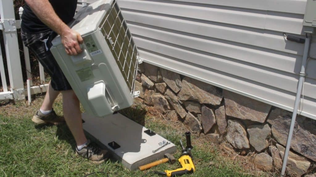
Setting Up the Outdoor Unit
Prepare a solid, level mounting surface for the outdoor condenser. Purpose-built AC mounting pads — made from pre-cast concrete or heavy-duty plastic — are the most common choice. Alternatively, you can pour a small concrete pad using two or three bags of concrete mix. Secure the unit to the pad using appropriately sized concrete anchors.
Leave slack in the copper lineset between the units. Unless you plan to cut and reflare the lines yourself, you will inevitably have excess tubing. Coil it neatly behind the outdoor unit or conceal it in a line cover. Using the factory-flared lineset kit is strongly recommended to avoid the risk of a poor field flare, which is the leading cause of refrigerant leaks in DIY installations.
Making the Lineset Connections
⚠ This Is the Most Critical Step
Leaking refrigerant connections are the single biggest risk in any mini split installation. Take your time here and do it right.
Both the indoor and outdoor units arrive factory-pressurized. The outdoor unit contains refrigerant sealed behind service valves, so you can access the flare fittings without releasing refrigerant. The indoor unit is typically pressurized with nitrogen. Before connecting the lineset, loosen the end caps on the indoor unit and listen for nitrogen escaping — this confirms the factory seal was intact. Allow the pressure to bleed down fully before proceeding. If the indoor unit is not pressurized, contact the manufacturer, as this may indicate a defect.
When making flare connections, ensure the copper tubing is properly aligned so the flare seats squarely against the fitting. Wiggle the hose gently to help the flare nut seat fully under hand tightness before reaching for a wrench. Your installation manual will specify a torque value for each flare nut size. Use a torque wrench with a crow's foot socket to tighten to that exact specification. Overtightening can distort the flare, while undertightening will cause leaks. Both scenarios are expensive mistakes.
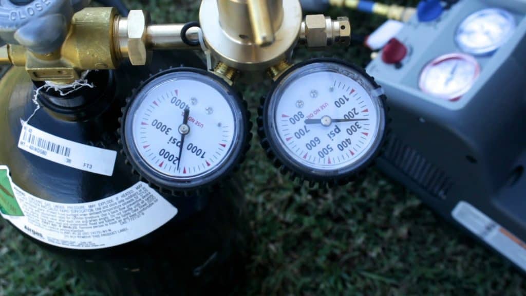
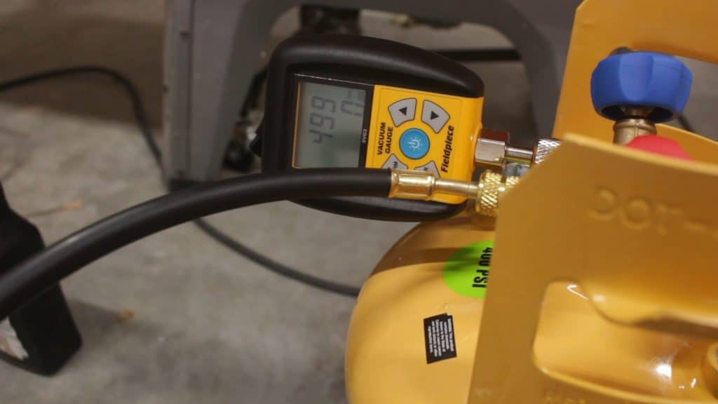
Pressure Testing with Nitrogen
Although some manufacturer instructions only require a vacuum test, a nitrogen pressure test provides an additional level of confidence that your connections are airtight. Pressurize the system with dry nitrogen to approximately 250 PSI — roughly the saturation pressure of R410a at room temperature — and monitor the pressure gauge for at least 12 hours.
Some pressure fluctuation is normal as ambient temperature changes overnight. A 20°F temperature swing can account for roughly 10 PSI of change. Use a nitrogen pressure calculator to determine expected variation. If your pressure holds steady within the expected thermal range over a 12 to 24 hour period, you can be confident your system is sealed.
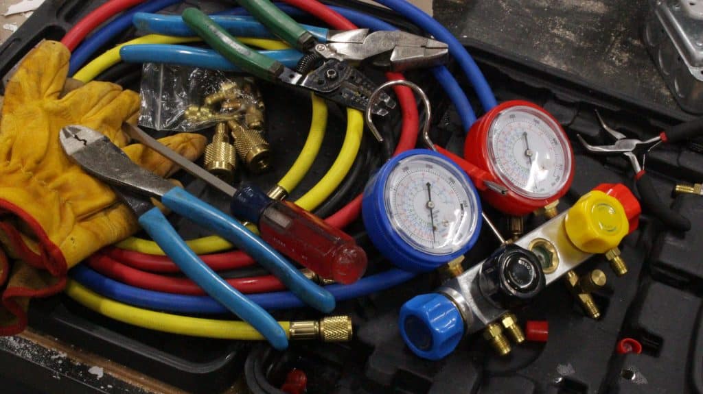
Manifold Gauge Connections
You will connect a manifold gauge set to the system's low-side service port using a 5/16-inch to 1/4-inch mini split adapter. The manifold provides connections for your vacuum pump, micron gauge, nitrogen supply, and the system itself — all through a central hub that allows you to manage each connection independently.
A low-loss fitting on the blue line helps minimize refrigerant escape when disconnecting hoses later. Hose-end ball valves are another option. Note that most residential mini splits only have a low-side service port — there is no high-side connection point. All evacuation, testing, and charging operations happen through this single port.
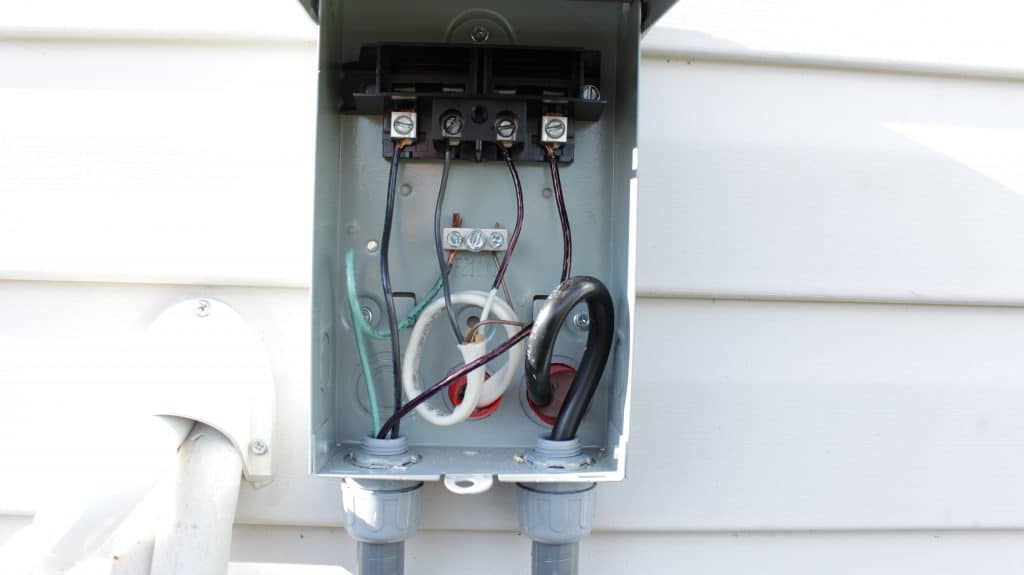
Electrical Wiring
Most mini split systems require a dedicated 240-volt circuit. Only work with de-energized conductors and equipment. Ensure your installation meets the current National Electrical Code and any additional local code requirements.
Install an electrical disconnect box near the outdoor unit. This allows the system to be isolated for service without walking back to the main panel. Size the supply circuit wire gauge and breaker to match the unit's specifications — for example, a unit rated for a maximum 15A fuse would require 14 AWG wire and a 15A two-pole breaker.
Route the indoor-to-outdoor communication cable from the indoor unit to the disconnect box and then onward to the outdoor unit. Mark any white conductors used as hot legs with black tape or marker to comply with code. Use wire rated for wet locations (such as THWN) for any outdoor runs, even if enclosed in liquid-tight conduit. Use spade lugs for stranded wire connections to terminal blocks for reliability.
Leave the final step — installing the two-pole breaker in your main panel — for absolute last, after everything else is connected and tested. De-energize the panel by opening the main breaker first. If that is not feasible, use appropriate personal protective equipment including insulating gloves, safety glasses, and a face shield. Land the ground wire first, then connect the two insulated conductors. Leave the breaker in the off position until the system is fully charged and ready for startup.
System Evacuation and Charging
Once the pressure test confirms your system is sealed, the next step is to remove all air and moisture from the lineset and indoor unit. Even tiny amounts of water vapor will damage the compressor over time. The industry-standard approach is a triple evacuation: pull a vacuum, break the vacuum with nitrogen, vent the nitrogen, and repeat the cycle two more times.
Use a two-stage vacuum pump and a micron gauge to verify the depth of your vacuum. Do not rely on the manifold gauges alone, and do not rely on simply timing how long the pump runs. You need to see actual micron readings. Professional installations target below 500 microns using large-diameter hoses and valve core removal tools. With standard 1/4-inch diameter hoses and a non-vacuum-rated manifold, achieving 1,000 to 1,500 microns is a realistic and acceptable target.
After reaching your target vacuum, isolate the pump and watch the micron gauge. Expect some creep as the vacuum equalizes throughout the system, but it should stabilize. A drift of a few hundred microns over 10 minutes is acceptable with non-vacuum-rated equipment. If the gauge climbs steadily without stabilizing, investigate for a leak — though this should be unlikely if your nitrogen pressure test held.
With the system evacuated and holding vacuum, follow the manufacturer's instructions to open the service valves on the outdoor unit and release the pre-charged refrigerant into the lineset and indoor unit. This is a point of no return. Once refrigerant is released, you cannot disconnect the lineset without first recovering all refrigerant from the system — a process that requires additional equipment.
Engage the outdoor disconnect, flip the breaker on at the main panel, and follow the manufacturer's startup sequence. When the system begins cooling or heating, the low-side pressure will drop, which provides an opportune moment to disconnect your adapter from the service port. Do this quickly and decisively to minimize refrigerant loss.
Common Mistakes and How to Fix Them
Even experienced DIYers make mistakes on their first mini split installation. The key is recognizing them early and knowing the correct course of action.
The Schrader Valve Trap
One of the most common first-timer mistakes involves the mini split adapter's Schrader valve. The adapter has a depressor on one end that opens the valve inside the mini split's service port, and a Schrader valve on the outward end that prevents refrigerant from escaping when nothing is connected. If the Schrader valve depressor on your hose fitting is not properly engaged, your vacuum pump will evacuate only the hose and manifold — not the actual system. Everything will appear to work fine until you release the refrigerant, at which point the pre-charged R410a mixes with the air and moisture still trapped in the unevacuated lineset.
Warning signs: The system reaches vacuum suspiciously fast (within a couple of minutes rather than 15+). When you crack the refrigerant valve, the manifold gauge does not register any pressure change.
Correcting a Contaminated Charge
If refrigerant has been released into an unevacuated system, the entire charge is contaminated with moisture and non-condensable gases. The system will not perform correctly and can be damaged over time. The fix is to recover all the refrigerant using a proper recovery machine and recovery cylinder, then perform a full triple evacuation and recharge with virgin refrigerant.
This is an expensive correction — a recovery unit, recovery cylinder, new tank of R410a, a nitrogen tank and regulator, and a micron gauge can add several hundred dollars to the project. However, it is absolutely the correct procedure. Contact the manufacturer to confirm the repair plan before proceeding.
The recovery process involves evacuating the recovery tank, connecting the recovery unit inline between the system and the recovery cylinder through a filter drier, and running the unit until the system reaches the EPA-specified minimum vacuum. Cooling the recovery cylinder (with ice or cool water) and ensuring the system is at ambient temperature speeds the process considerably. Weigh the recovery cylinder before and after to track how much refrigerant was recovered.
Recharging with Virgin Refrigerant
With EPA certification, you can purchase a tank of virgin R410a from a local HVAC supply house. After completing your triple evacuation and confirming the system holds vacuum, connect the refrigerant tank to the manifold gauge set. Place the tank upside down on a scale. R410a must always be charged in liquid form from an inverted tank because it is a blended refrigerant — charging from the vapor phase will change the blend ratio.
Calculate your target weight by subtracting the system's specified charge weight from the starting weight of the tank. Open the valves carefully and watch the scale as liquid refrigerant flows into the system. As you approach the target weight, flow will slow. Gently warming the tank with a heat gun can help transfer those final grams. Once you hit the target weight, close the tank valve and isolate the system from the manifold.
![]()
Cost Breakdown
A straightforward DIY mini split installation — where nothing goes sideways — typically costs around $1,250 to $1,500 for the unit, lineset, permits, and basic tools. Add EPA certification and you are looking at roughly $1,350 to $1,600 total.
If you encounter a complication like a contaminated charge and need to purchase recovery equipment and a fresh tank of refrigerant, expect to add another $400 to $600. Even with this setback, the total remains well under what a professional installation typically costs.
The real payoff comes on the next installation. With all the tools already in hand and the experience under your belt, a second installation can be completed in a single weekend for roughly the cost of the unit, lineset, and permit — roughly $1,250 all in.
Real-World Performance Observations
A properly installed high-efficiency inverter mini split delivers impressive results. In real-world use, an installed unit has been able to reliably hold indoor temperatures at a comfortable 72 to 75°F even when afternoon outdoor temperatures reach 95°F. On milder days with outdoor highs around 85°F, indoor temperatures can drop as low as 65°F with ease.
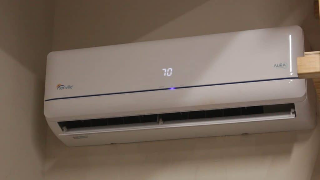
One thing that surprises many first-time mini split owners is that a high-efficiency inverter unit runs nearly continuously. This is by design. Rather than cycling on and off like a traditional HVAC system, the inverter throttles the compressor speed down to match the load. This may seem counterintuitive if you grew up with conventional systems that kick on every 20 minutes and blast cold air, but continuous low-speed operation is actually more efficient and maintains a more consistent temperature.
You may notice the room temperature settles about 1 to 2 degrees above the display setpoint. This can be the result of minor calibration differences between the unit's sensor and an external thermometer, or it may be intentional — by keeping the temperature just above the target, the inverter avoids overshooting and having to shut off entirely, preserving the efficiency advantage.
The built-in timer functions are a welcome convenience. If you do not use the space every day, program the unit to turn on an hour before you arrive so the room is already comfortable when you walk in. Set the off-timer for when you leave to avoid running the system unnecessarily. These small habits can measurably reduce energy consumption over the course of a season.
A DIY mini split installation is one of the most rewarding home improvement projects you can tackle. It requires genuine skill and careful preparation, but the combination of significant cost savings, a deep understanding of your own system, and the satisfaction of doing it with your own hands makes it well worth the effort. Document everything, follow the manufacturer's instructions, and take your time with the critical steps. Your future self — enjoying a perfectly climate-controlled space — will thank you.
Ready to get started? The Senville LETO series offers the performance, efficiency, and DIY-friendly design that makes a self-installed system a real possibility for handy homeowners.